A frequency comb transforms a single optical carrier into a set of regularly spaced spectral lines. They can use those lines as parallel references, measurement rulers, wavelength sources, or building blocks for signal synthesis.
The concept is capable because spacing and coherence can be controlled, but useful performance depends on far more than producing a visually broad spectrum. Electro-optic generation applies a periodic electrical drive to one or more modulators, creating sidebands around the laser frequency. Repeated modulation or cascaded stages can expand and shape the line set.
Compared with some cavity-based approaches, an electro-optic architecture can offer direct control of spacing through the RF source and can integrate naturally with communication and microwave equipment.
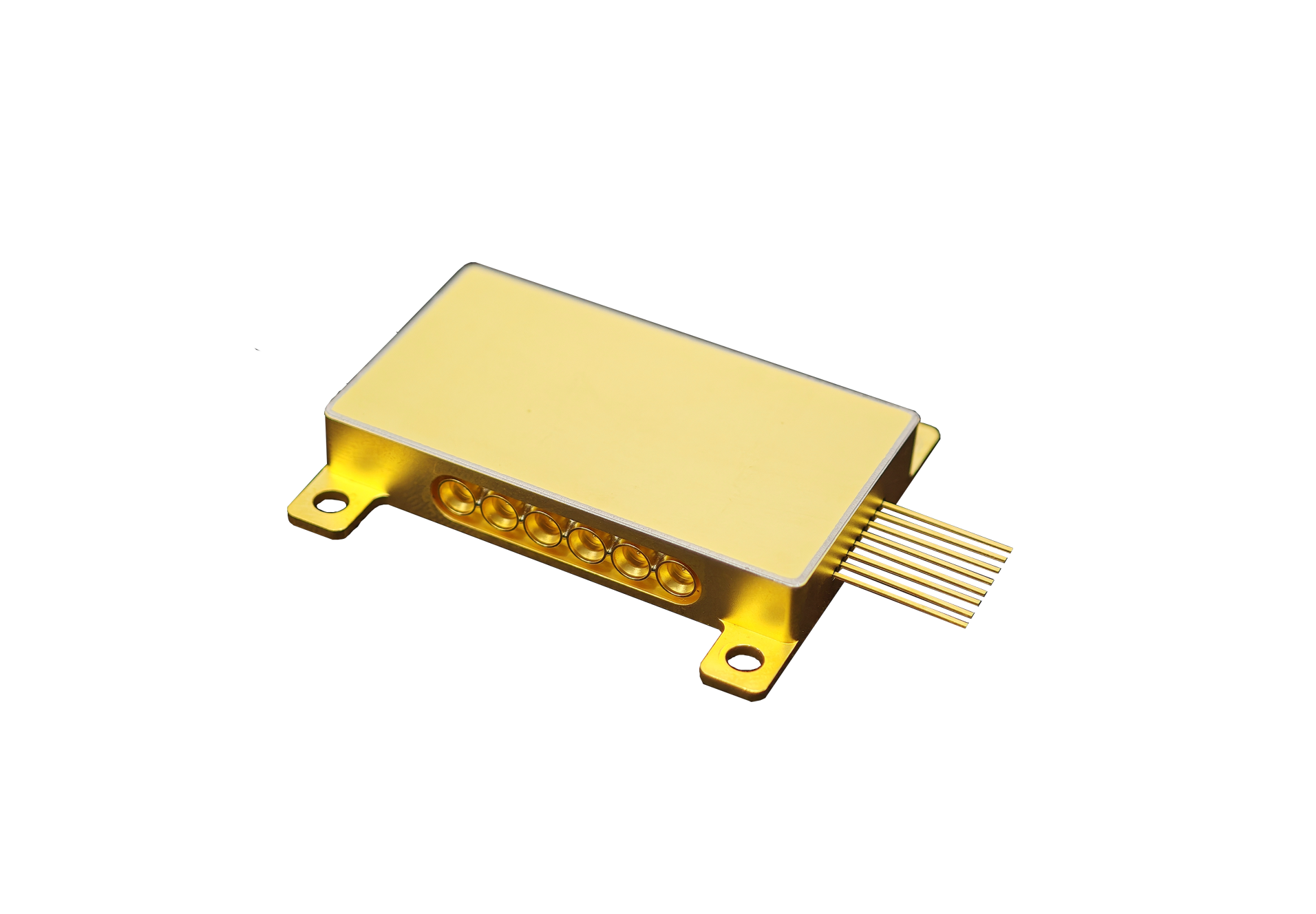
The published family of TFLN devices includes a compact comb product with 25 GHz RF bandwidth, half-wave voltage below 2.5 V, insertion loss below 9 dB, and a customizable three-level configuration. They treat these figures as boundary conditions for system design, then evaluate line count, flatness, optical power, phase behavior, and stability in the intended application.
Comb Generation Converts One Laser into a Structured Spectrum
An optical frequency comb begins with a narrow, stable laser and a modulation chain that creates equally spaced frequency components. Phase modulation generates sidebands, while intensity or additional phase stages can shape the envelope.
The RF frequency sets the nominal spacing, so the microwave source, amplifier, cables, and termination become part of the optical-frequency architecture. TFLN devices are relevant because their electro-optic efficiency and bandwidth can support sideband generation with manageable drive requirements. The thin-film platform also permits compact circuits that combine several modulation functions.
They still calculate available RF power, optical damage limits, and thermal behavior, since laboratory comb breadth achieved under one condition may not be sustainable in a packaged commercial setup. Multi-level configuration can increase design flexibility.
Different stages may be driven with selected amplitudes and phases to improve line count or spectral flatness. They define the control parameters that must remain stable and determine whether they can be calibrated automatically. A configuration that needs frequent manual adjustment may be unsuitable for unattended measurement or production use.
Practical Benefits Depend on Line Quality and Drive Conditions
Line spacing is usually the starting system parameter because it determines resolution, channel separation, or synthesis increments. A 25 GHz RF bandwidth supports a particular class of spacing and drive arrangements, yet the usable optical frequency comb also depends on modulator response at the exact operating frequency.
They verify amplitude and phase response rather than assuming the nominal bandwidth guarantees uniform operation. Insertion loss below 9 dB must be placed in the optical-power budget. Laser output, connector loss, modulation loss, subsequent filtering, and detector sensitivity determine whether lower-power comb lines remain usable.
When assessing TFLN devices, they examine both total power and power per line because a broad spectrum may distribute energy so widely that edge lines have insufficient signal-to-noise ratio. Half-wave voltage below 2.5 V indicates electro-optic efficiency, but required RF power depends on impedance, waveform, stage count, and target modulation index.
They model amplifier compression, heat, and phase noise. Stronger drive can generate more sidebands while also increasing distortion or reliability stress, so the optimum operating point should be established experimentally for the chosen line-quality requirement.
Application Qualification Must Include the Entire Optical Setup
Qualification criteria depend on the intended use of the optical frequency comb. Spectroscopy values accurate frequency placement, stable spacing, and known line power. Precision synthesis may emphasize phase coherence and traceability to an RF reference, while communication experiments may prioritize many carriers with controlled flatness.
For each use, the optical frequency comb must be qualified with metrics that reflect the actual measurement or transmission error, not a generic spectrum image. TFLN devices should be tested together with the laser, RF source, amplifier, polarization control, filters, and receiver. They perform warm-up, temperature, vibration, and long-duration measurements where relevant.
Automated acquisition helps separate slow drift from random noise and shows whether recalibration intervals are compatible with operating procedures and customer expectations. Commercialization requires a reproducible calibration and service plan. They document RF settings, optical input limits, connector handling, reference equipment, and acceptance thresholds.
Spare-unit interchangeability is important: a replacement should meet the application without an extensive redevelopment cycle. Supplier change control must cover components and assembly steps that can influence insertion loss or high-frequency response. The principal benefit of an electro-optic comb is controllability.
Spacing can follow an electronic reference, modulation stages can be configured for a target spectrum, and the optical output can support several measurement or communication functions. That controllability has practical value when line power, phase behavior, drift, and calibration effort remain within documented limits.
They recommend beginning with an application-specific error budget. It should connect laser stability, RF phase noise, modulator response, loss, line flatness, receiver noise, and software processing. A prototype can then identify which parameter truly limits the result, avoiding unnecessary expense on specifications that do not improve the intended measurement or synthesis task.
Comb performance emerges from the interaction of the optical circuit, RF drive, coupling, temperature, and measurement method. A controlled prototype using a Liobate TFLN device can turn those interactions into spectral and repeatability data for the package and test teams.
